Configuring DHCP
CHAPTERS
4. DHCP L2 Relay Configuration
6. Appendix: Default Parameters
|
|
This guide applies to: T1600G-18TS v2 or above, T1600G-28TS v3 or above, T1600G-28PS v3 or above, T1600G-52TS v3 or above, T1600G-52PS v3 or above, T1700X-16TS v3 or above, T1700G-28TQ v3 or above, T2600G-18TS v2 or above, T2600G-28TS v3 or above, T2600G-28MPS v3 or above, T2600G-28SQ v1 or above, T2600G-52TS v3 or above. |

1.1Overview
DHCP (Dynamic Host Configuration Protocol) is widely used to automatically assign IP addresses and other network configuration parameters to network devices, enhancing the utilization of IP address.
1.2Supported Features
The supported DHCP features of the switch include DHCP Server, DHCP Relay and DHCP L2 Relay.
DHCP Server
DHCP Server is used to dynamically assign IP addresses, default gateway and other parameters to DHCP clients. As the following figure shows, the switch acts as a DHCP server and assigns IP addresses to the clients.
Figure 1-1 Application Scenario of DHCP Server

DHCP Relay
DHCP Relay is used to process and forward DHCP packets between different subnets or VLANs.
The DHCP client broadcasts DHCP request packets to require for an IP address. Since the transmission of broadcast packets are always limited in one LAN, so if the DHCP server are not in the same LAN with the client, the client can never obtain an IP address from the DHCP server. Therefore, each LAN should be equipped with a DHCP server, thus increasing the costs of network construction and bringing trouble for central network management.
DHCP Relay solves this problem. The DHCP Relay device acts as a relay agent and forwards DHCP packets between DHCP clients and DHCP servers in different LANs, so that DHCP clients in different LANs can share one DHCP server.
DHCP Relay includes three features: Option 82, DHCP Interface Relay and DHCP VLAN Relay.
Option 82
The switch can record the location information of the DHCP client using Option 82. The switch can add Option 82 to the DHCP request packet and then transmit the packet to the DHCP server. The DHCP server which supports Option 82 can set the distribution policy of IP addresses and the other parameters, providing a more flexible address distribution way.
DHCP Interface Relay
DHCP Interface Relay is used for the clients in different subnets to obtain IP addresses from the DHCP server that is not in the same subnet as the clients.
In DHCP Interface Relay, you can specify a DHCP server for an Layer 3 interface that the clients are connected to. When receiving DHCP packets from clients, the switch will fill the corresponding interface’s IP address in the relay agent IP address field of the DHCP packets, and forwards the packets to the DHCP server. The DHCP server assigns IP addresses to the clients based on the relay agent IP address field.
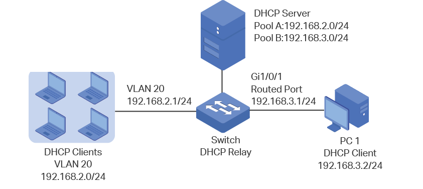
As the following figure shows, the IP address for VLAN20 is 192.168.2.1/24 and for the routed port Gi1/0/1 is 192.168.3.1/24. With DHCP Interface VLAN configured, the switch uses IP address of VLAN 20 (192.168.2.1/24) when applying for IP addresses for clients in VLAN 20, and uses IP address of Gi1/0/1 (192.168.3.1/24) when applying for IP address for PC 1. As a result, the DHCP server will assign IP addresses in Pool A (the same subnet with the IP address of VLAN 20) to clients in VLAN 20, and assign IP address in Pool B (the same subnet with the Gi1/0/1) to PC 1.
Figure 1-2 Application Scenario of DHCP Interface Relay
DHCP VLAN Relay
DHCP VLAN Relay allows clients in different VLANs to obtain IP addresses from the DHCP server using a single agent interface IP address.
In DHCP Interface Relay, to assign IP addresses to clients in different VLANs, you need to create a layer 3 interface for each VLAN to ensure the reachability.
In DHCP VLAN Relay, you can simply specify a layer 3 interface as default agent interface for all VLANs. The swith will fill this default agent interface’s IP address in the relay agent IP address field of the DHCP packets from all VLANs.
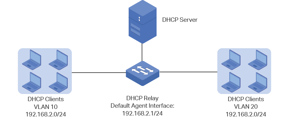
As the following figure shows, no IP addresses are assigned to VLAN 10 and VLAN 20, but a default relay agent interface is configured with the IP address 192.168.2.1/24. The switch uses IP address of the default agent interface (192.168.2.1/24) to apply for IP addresses for clients in both VLAN 10 and VLAN 20. As a result, the DHCP server will assign IP addresses on 192.168.2.0/24 (the same subnet with the IP address of the default agent interface) to clients in both VLAN 10 and VLAN 20.
Figure 1-3 Application Scenario of DHCP VLAN Relay
|
|
Note: If the VLAN already has an IP address, the switch will use the IP address of the VLAN as the relay agent IP address. The default relay agent IP address will not take effect. A routed port or port channel interface is not associated with a particular VLAN. DHCP VLAN relay will not work on routed ports or port channel interfaces. |

DHCP L2 Relay
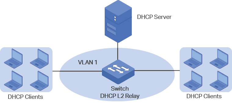
Unlike DHCP relay, DHCP L2 Relay is used in the situation that the DHCP server and client are in the same VLAN. In DHCP L2 Relay, in addition to normally assigning IP addresses to clients from the DHCP server, the switch can record the location information of the DHCP client using Option 82. The switch can add Option 82 to the DHCP request packet and then transmit the packet to the DHCP server. The DHCP server which supports Option 82 can set the distribution policy of IP addresses and the other parameters, providing a more flexible address distribution way.
Figure 1-4 Application Scenario of DHCP L2 Relay
To complete DHCP server configuration, follow these steps:
1)Enable the DHCP Server feature on the switch.
2)Configure the DHCP Server Pool.
3)(Optional) Manually assign static IP addresses for some clients if necessary.
2.1Using the GUI
2.1.1Enabling DHCP Server
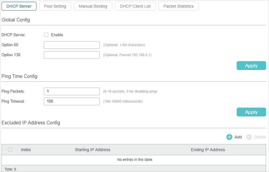
Choose the menu L3 FEATURES > DHCP Service > DHCP Server > DHCP Server to load the following page.
Figure 2-1 DHCP Server
Follow these steps to configure DHCP Server:
1)In the Global Config section, enable DHCP Server. Click Apply.
|
DHCP Server |
Enable DHCP Server. By default, it is disabled. |
|
Option 60 |
(Optional) Specify the option 60 for device identification. Mostly it is used in the scenario where the APs (Access Points) apply for different IP addresses from different servers according to the needs. If an AP requests option 60, the server will respond a packet containing the option 60 configured here. And then the AP will compare the received option 60 with its own. If they are the same, the AP will accept the IP address assigned by the server, otherwise the assigned IP address will not be accepted. |
|
Option 138 |
(Optional) Specify the option 138, which can be configured as the management IP address of an AC (Access Control) device. If the APs in the local network request this option, the server will respond a packet containing this option to inform the APs of the AC’s IP address. |
2)In the Ping Time Config section, configure Ping Packets and Ping Timeout for ping tests. Click Apply.
|
Ping Packets |
Enter the number of ping packets the server can broadcast to test whether the IP address is occupied. The valid values are from 1 to 10, and the default is 1. When the switch is configured as a DHCP server to dynamically assign IP addresses to clients, the switch will deploy ping test to avoid IP address conflict resulted from assigning IP addresses repeatedly. |
|
Ping Timeout |
Specify the ping timeout period in milliseconds. It ranges from 100 to 10000 ms and the default is 100 ms. The DHCP server broadcasts an ICMP Echo Request (ping packet) to test whether an IP address is occupied or not. If the number of ping packets reaches the specified number and there is still no response, the server will assign the IP address. Otherwise, the server will record the IP address as a conflicted IP address and assign another IP address to the client. |
3)In the Excluded IP Address Table section, click  to load the following page to specify the IP addresses that should not be assigned to the clients.
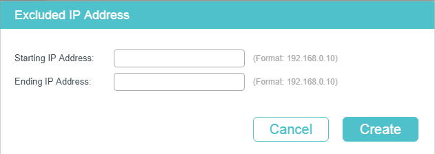
Enter the Starting IP Address and Ending IP Address to specify the range of reserved IP addresses. Click Create.
|
Starting IP Address/ Ending IP Address |
Specify the start IP address and end IP address of the excluded IP address range. If the start IP address and the end IP address are the same, the server excludes only one IP address. When configuring DHCP Server, you need to reserve certain IP addresses for each subnet, such as default gateway address, broadcast address and DNS server address. |
2.1.2Configuring DHCP Server Pool
The DHCP Server Pool defines the parameters that will be assigned to the DHCP clients.
Choose the menu L3 FEATURES > DHCP Service >DHCP Server > Pool Setting and click to load the following page.
Figure 2-2 Pool Setting
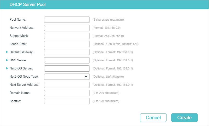
Configure the parameters for the DHCP Server Pool. Then click Create.
|
Pool Name |
Specify a pool name for identification. |
|
Network Address / Subnet Mask |
Configure the network address and subnet mask of the DHCP server pool. The network address and subnet mask decide the range of the DHCP server pool. On the same subnet, all addresses can be assigned except the excluded addresses and addresses for special uses. |
|
Lease Time |
Specify how long the client can use the IP address assigned from this address pool. It ranges from 1 to 2880 minutes and the default is 120 minutes. |
|
Default Gateway |
(Optional) Configure the default gateway of the DHCP server pool. You can create up to 8 default gateways for each DHCP server pool. If you leave this field blank, the DHCP server will not assign this parameter to the client. In general, you can configure the IP address of the VLAN interface as the default gateway address. |
|
DNS Server |
(Optional) Specify the DNS server of the DHCP server pool. You can specify up to 8 DNS servers for each DHCP server pool. If you leave this field blank, the DHCP server will not assign this parameter to the client. In general, you can configure the IP address of the VLAN interface as the DNS server address. |
|
Netbios Server |
(Optional) Specify the NetBIOS name server. You can specify up to 8 NetBIOS servers for each DHCP server pool. If you leave this field blank, the DHCP server will not assign this parameter to the client. When a DHCP client uses the Network NetBIOS (Basic Input Output System) protocol for communication, the host name must be mapped to IP address. NetBIOS name server can resolve host names to IP addresses. |
|
Netbios Node Type |
(Optional) Specify the Netbios type for the clients, which is the way of inquiring IP address resolution. If you leave this field blank, the DHCP server will not assign this parameter to the client. The following options are provided: b-node Broadcast: The client sends query message via broadcast. p-node Peer-to-Peer: The client sends query message via unicast. m-node Mixed: The client sends query message via broadcast first. If it fails, the client will try again via unicast. h-node Hybrid: The client sends query message via unicast first. If it fails, the client will try again via broadcast. |
|
Next Server Address |
(Optional) Specify the IP address of a TFTP server for the clients. If needed, the clients can get the configuration file from the TFTP server for auto installation. If you leave this field blank, the DHCP server will not assign this parameter to the client. |
|
Domain Name |
(Optional) Specify the domain name that the clients should use when resolving host names via DNS. If you leave this field blank, the DHCP server will not assign this parameter to the client. |
|
Bootfile |
(Optional) Specify the name of the bootfile. If needed, the clients can get the bootfile from the TFTP server for auto installation. If you leave this field blank, the DHCP server will not assign this parameter to the client. |
2.1.3Configuring Manual Binding
Some devices like web servers require static IP addresses. To meet this requirement, you can manually bind the MAC address or client ID of the device to an IP address, and the DHCP server will reserve the bound IP address to this device at all times.
Choose the menu L3 FEATURES > DHCP Service >DHCP Server > Manual Binding and click to load the following page.
Figure 2-3 Manual Binding
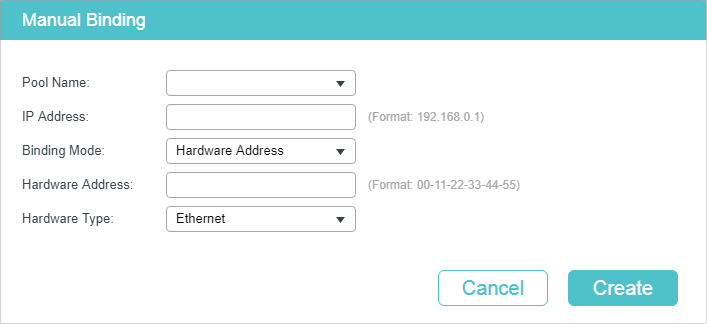
Select a pool name and enter the IP address to be bound. Select a binding mode and finish the configuration accordingly. Click Create.
|
Pool Name |
Select a DHCP server pool from the drop-down list. |
|
IP Address |
Enter the IP address to be bound to the client. |
|
Binding Mode |
Select the binding mode: Client ID: Bind the IP address to the client ID of the client. Client ID in ASCII: Bind the IP address to the client ID in ASCII format. Hardware Address: Bind the IP address to the MAC address of the client. |
|
Client ID |
If you select Client ID as the binding mode, enter the client ID in this field. |
|
Hardware Address |
If you select Hardware Address as the binding mode, enter the MAC address in this field. |
|
Hardware Type |
If you select Hardware Address as the binding mode, select a hardware type. The hardware type includes Ethernet and IEEE802. |
2.2Using the CLI
2.2.1Enabling DHCP Server
Follow these steps to enable DHCP Server and to configure ping packets and ping timeout.
|
Step 1 |
configure Enter global configuration mode. |
|
Step 2 |
service dhcp server Enable DHCP Server. |
|
Step 3 |
ip dhcp server extend-option vendor-class-id vender (Optional) Specify the option 60 for server identification. If a client requests option 60, the server will respond a packet containing the option 60 configured here. And then the client will compare the received option 60 with its own. If they are the same, the client will accept the IP address assigned by the server, otherwise the assigned IP address will not be accepted. vender: Specify the option 60. |
|
Step 4 |
ip dhcp server extend-option capwap-ac-ip ip-address (Optional) Specify the option 138, which can be configured as the management IP address of an AC (Access Control) device. If the APs (Access Points) in the local network request this option, the server will respond a packet containing this option to inform the APs of the AC’s IP address. ip-address: Specify the option 138. |
|
Step 5 |
ip dhcp server ping timeout value Specify the ping timeout period. The DHCP server broadcasts an ICMP Echo Request (ping packet) to test whether an IP address is occupied or not. If there is no response within the ping timeout period, the server will broadcast the ping packet again. If the number of ping packets reaches the specified number and there is still no response, the server will assign the IP address. Otherwise, the server will record the IP address as a conflicted IP address and assign another IP address to the client. value: Specify the ping timeout period in milliseconds. It ranges from 100 to 10000 ms and the default is 100 ms. |
|
Step 6 |
ip dhcp server ping packets num Specify the number of ping packets the server can broadcast to test whether the IP address is occupied. When the switch is configured as a DHCP server to dynamically assign IP addresses to clients, the switch will deploy ping test to avoid IP address conflict resulted from assigning IP addresses repeatedly. num: Enter the number of ping packets. The valid values are from 1 to 10, and the default is 1. |
|
Step 7 |
ip dhcp server exclude-address start-ip-address end-ip-address Specify the starting IP address and ending IP address of the excluded IP address range. If the starting IP address and the ending IP address are the same, the server excludes only one IP address. When configuring DHCP Server, you need to reserve certain IP addresses for each subnet, such as default gateway address, broadcast address and DNS server address. start-ip-address/end-ip-address: Specify the starting IP address and ending IP address. |
|
Step 8 |
show ip dhcp server status Verify the DHCP status, including whether it is enabled and the configuration of ping packet number and ping packet timeout. |
|
Step 9 |
show ip dhcp server extend-option Verify the configuration of the extend options. |
|
Step 10 |
show ip dhcp server excluded-address Verify the configuration of the excluded IP address. |
|
Step 11 |
end Return to Privileged EXEC Mode. |
|
Step 12 |
copy running-config startup-config Save the settings in the configuration file. |
The following example shows how to enable DHCP Server globally on Switch, configure the number of ping packets as 2 and configure the ping timeout period as 200 ms:
Switch#configure
Switch(config)#service dhcp server
Switch(config)#ip dhcp server ping packets 2
Switch(config)#ip dhcp server ping timeout 200
Switch(config)#show ip dhcp server status
DHCP server is enable.
Ping packet number: 2.
Ping packet timeout: 200 milliseconds.
Switch(config)#end
Switch#copy running-config startup-config
The following example shows how to configure the option 60 as abc and option 138 as 192.168.0.155:
Switch#configure
Switch(config)#ip dhcp server extend-option vendor-class-id abc
Switch(config)#ip dhcp server extend-option capwap-ac-ip 192.168.0.155
Switch(config)#show ip dhcp server extend-option
Option 60: abc
Option 138: 192.168.0.155
Switch(config)#end
Switch#copy running-config startup-config
The following example shows how to configure the 192.168.1.1 as the default gateway address and excluded IP address:
Switch#configure
Switch(config)#ip dhcp server excluded-address 192.168.1.1 192.168.1.1
Switch(config)#show ip dhcp server excluded-address
No. Start IP Address End IP Address
--- ------------- --------------
1 192.168.1.1 192.168.1.1
Switch(config)#end
Switch#copy running-config startup-config
2.2.2Configuring DHCP Server Pool
Follow these steps to configure DHCP server pool:
|
Step 1 |
configure Enter global configuration mode. |
|
Step 2 |
ip dhcp server pool pool-name Configure a name for the DHCP server pool for identification. pool-name: Specify a pool name with 1 to 8 characters. |
|
Step 3 |
network network-address subnet-mask Configure the network address and subnet mask of the DHCP server pool. The network address and subnet mask decide the range of the DHCP server pool. On the same subnet, all addresses can be assigned except the excluded addresses and addresses for special uses. network-address: Configure the network address of the DHCP server pool. subnet-mask: Configure the subnet mask of the DHCP server pool. |
|
Step 4 |
lease lease-time Specify how long the client can use the IP address assigned from this address pool. lease-time: Enter the value of lease-time. It ranges from 1 to 2880 minutes and the default is 120 minutes. |
|
Step 5 |
default-gateway gateway-list (Optional) Configure the default gateway of the DHCP server pool. In general, you can configure the IP address of the VLAN interface as the default gateway address. gateway-list: Specify the IP address of the default gateway. You can create up to 8 default gateways for each DHCP server pool. |
|
Step 6 |
dns-server dns-server-list (Optional) Specify the DNS server of the DHCP server pool. In general, you can configure the IP address of the VLAN interface as the DNS server address. dns-server-list: Specify the IP address of the DNS server. You can specify up to 8 DNS servers for each DHCP server pool. |
|
Step 7 |
netbios-name-server NBNS-list (Optional) Specify the NetBIOS name server. You can specify up to 8 NetBIOS servers for each DHCP server pool. When a DHCP client uses the Network NetBIOS (Basic Input Output System) protocol for communication, the host name must be mapped to IP address. NetBIOS name server can resolve host names to IP addresses. NBNS-list: Specify the IP address of the NetBIOS server. You can specify up to 8 NetBIOS servers for each DHCP server pool. |
|
Step 8 |
netbios-node-type type (Optional) Specify the Netbios type for the clients, which is the way of inquiring IP address resolution. type: Specify the Netbios type. The following options are provided: b-node Broadcast: The client sends query message via broadcast. p-node Peer-to-Peer: The client sends query message via unicast. m-node Mixed: The client sends query message via broadcast first. If it fails, the client will try again via unicast. h-node Hybrid: The client sends query message via unicast first. If it fails, the client will try again via broadcast. |
|
Step 9 |
next-server ip-address (Optional) Specify the IP address of a TFTP server for the clients. If needed, the clients can get the configuration file from the TFTP server for auto installation. ip-address: Specify the IP address of theTFTP server. |
|
Step 10 |
domain-name domainname (Optional) Specify the domain name that the clients should use when resolving host names via DNS. domainname: Specify the domain name. |
|
Step 11 |
bootfile file-name (Optional) Specify the name of the bootfile. If needed, the clients can get the bootfile from the TFTP server for auto installation. file-name: Specify the bootfile name. |
|
Step 12 |
show ip dhcp server pool Verify the configuration of the DHCP server pool. |
|
Step 13 |
end Return to Privileged EXEC Mode. |
|
Step 14 |
copy running-config startup-config Save the settings in the configuration file. |
The following example shows how to create a DHCP server pool and name it as pool1 and configure its network address as 192.168.1.0, subnet mask as 255.255.255.0, lease time as 180 minute, default gateway as 192.168.1.1, DNS server as 192.168.1.4, Netbios server as 192.168.1.19, Netbios type as broadcast, TFTP server as 192.168.1.30, domain name as com, and bootfile name as bootfile:
Switch#configure
Switch(config)#ip dhcp server pool pool1
Switch(dhcp-config)#network 192.168.1.0 255.255.255.0
Switch(dhcp-config)#lease 180
Switch(dhcp-config)#default-gateway 192.168.1.1
Switch(dhcp-config)#dns-server 192.168.1.4
Switch(dhcp-config)#netbios-name-server 192.168.1.19
Switch(dhcp-config)#netbios-node-type b-node
Switch(dhcp-config)#next server 192.168.1.30
Switch(dhcp-config)#domain-name com
Switch(dhcp-config)#bootfile bootfile
Switch(dhcp-config)#show ip dhcp server pool
Pool Name: pool1
Network Address: 192.168.1.0
Subenet Mask: 255.255.255.0
Lease Time: 180
Default Gateway: 192.168.1.1
DNS Server: 192.168.1.4
Netbios Server: 192.168.1.19
Netbios Node Type: b-node
Next Server Address: 192.168.1.30
Domain Name: com
Bootfile Name: bootfile
Switch(dhcp-config)#end
Switch#copy running-config startup-config
2.2.3Configuring Manual Binding
Some hosts, WWW server for example, requires a static IP address. To satisfy this requirement, you can manually bind the MAC address or client ID of the host to an IP address, and the DHCP server will reserve the bound IP address to this host at all times.
Follow these steps to configure Manual Binding:
|
Step 1 |
configure Enter global configuration mode. |
|
Step 2 |
ip dhcp server pool name Create a DHCP server pool and enter DHCP configuration mode. |
|
Step 3 |
Bind an IP address to a client: address ip-address client-identifier client-id Bind the specified IP address to the client with a specific hexadecimal client ID. ip-address: Specify the IP address to be bound. client-id: Specify the client ID in hexadecimal format. address ip-address client-identifier client-id ascii Bind the specified IP address to the client with a specific ASCII client ID. ip-address: Specify the IP address to be bound. client-id: Specify the client ID with ASCII characters. address ip-address hardware-address hardware-address hardware-type { ethernet | ieee802 } Bind the specified IP address to the client with a specific MAC address. ip-address: Specify the IP address to be bound. hardware-address: Enter the MAC address of the client. ethernet | ieee802: Specify a hardware type for the client, either Ethernet or IEEE802. |
|
Step 4 |
show ip dhcp server manual-binding Verify the manual binding configuration. |
|
Step 5 |
end Return to Privileged EXEC Mode. |
|
Step 6 |
copy running-config startup-config Save the settings in the configuration file. |
The following example shows how to bind the IP address 192.168.1.33 in pool1 (on the subnet of 192.168.1.0) to the host with the MAC address 74:D4:68:22:3F:34:
Switch#config
Switch(config)#ip dhcp server pool pool1
Switch(dhcp-config)#address 192.168.1.33 hardware-address 74:d4:68:22:3f:34 hardware-type ethernet
Switch(dhcp-config)#show ip dhcp server manual-binding
Pool Name Client Id/Hardware Address IP Address Hardware Type Bind Mode
------- ------------------- --------- ----------- --------
pool1 74:d4:68:22:3f:34 192.168.1.33 Ethernet MAC Address
Switch(dhcp-config)#end
Switch#copy running-config startup-config
To complete DHCP Relay configuration, follow these steps:
1)Enable DHCP Relay. Configure Option 82 if needed.
2)Specify DHCP server for the Interface or VLAN.
3.1.1Enabling DHCP Relay and Configuring Option 82
Choose the menu L3 FEATURES > DHCP Service > DHCP Relay > DHCP Relay Config to load the following page.
Figure 3-1 Enable DHCP Relay and Configure Option 82
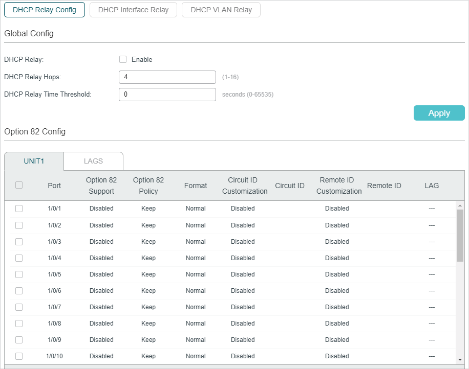
Follow these steps to enable DHCP Relay and configure Option 82:
1)In the Global Config section, enable DHCP Relay globally and configure the relay hops and the time threshold. Click Apply.
|
DHCP Relay |
Enable DHCP Relay globally. |
|
DHCP Relay Hops |
Specify the DHCP relay hops. DHCP Relay Hops defines the maximum number of hops (DHCP Relay agent) that the DHCP packets can be relayed. If a packet’s hop count is more than the value you set here, the packet will be dropped. |
|
DHCP Relay Time Threshold |
Specify the DHCP relay time threshold. The valid value ranges from 0 to 65535 seconds. DHCP relay time is the time elapsed since client began address acquisition or renewal process. When the time is greater than the value set here, the DHCP packet will be dropped by the switch. Value 0 means the switch will not examine this field of the DHCP packets. |
2)(Optional) In the Option 82 Configuration section, configure Option 82.
|
Option 82 Support |
Select whether to enable Option 82 or not. By default, it is disabled. Option 82 is used to record the DHCP client’s location, Ethernet port and the VLAN, etc. If you need to record the accurate location of a client, you can enable Option 82 on the relay device which is closest to the client. |
|
Option 82 Policy |
Select the operation for the Option 82 field of the DHCP request packets. Keep: Indicates keeping the Option 82 field of the packets. Replace: Indicates replacing the Option 82 field of the packets with the switch defined one. By default, the Circuit ID is defined to be the VLAN and the ID of the port which receives the DHCP Request packets. The Remote ID is defined to be the MAC address of the DHCP Relay device which receives the DHCP Request packets. Drop: Indicates discarding the packets that include the Option 82 field. |
|
Format |
Select the format of option 82 sub-option value field. Normal: Indicates that the format of sub-option value field is TLV (type-length-value). Private: Indicates that the format of sub-option value field is just value. |
|
Circuit ID Customization |
Enable or disable Customization of Option 82. If enabled, you need to configure Option 82 information manually; If disabled, the switch will automatically configure the VLAN ID and the ID of the port that receives the DHCP packets as the circuit ID. |
|
Circuit ID |
Enter the customized circuit ID, which contains up to 64 characters. The circuit ID configurations of the switch and the DHCP server should be compatible with each other. |
|
Remote ID Customization |
Enable or disable the switch to define the Option 82 sub-option Remote ID field. If it is enabled, you can manually configure the remote ID; if it is disabled, the switch will automatically configure the switch’s MAC address as the remote ID. |
|
Remote ID |
Enter the customized remote ID, which contains up to 64 characters. The remote ID configurations of the switch and the DHCP server should be compatible with each other. |
3)Click Apply.
3.1.2Configuring DHCP Interface Relay
DHCP Interface Relay is used for the clients that are connected to a Layer 3 interface to obtain IP addresses from the DHCP server, which is not in the same subnet as the clients.
Choose the menu L3 FEATURES > DHCP Service > DHCP Relay > DHCP Interface Relay and click to load the following page.
Figure 3-2 Configuring DHCP Interface Relay
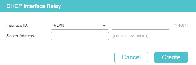
Select the interface type and enter the interface ID, then enter the IP address of the DHCP server. Click Create.
|
Interface ID |
Specify the type and ID of the interface. It is the layer 3 interface that connecting to the DHCP clients. The interface should be an existing layer 3 interface. |
|
Server Address |
Enter the IP address of the DHCP server. |
3.1.3Configuring DHCP VLAN Relay
DHCP VLAN Relay is used for the clients in VLANs but do not have a layer 3 interface as the gateway to obtain IP addresses from the DHCP server, which is not in the same subnet as the clients.
Choose the menu L3 FEATURES > DHCP Service > DHCP Relay > DHCP VLAN Relay to load the following page.
Figure 3-3 Specify DHCP Server for VLAN
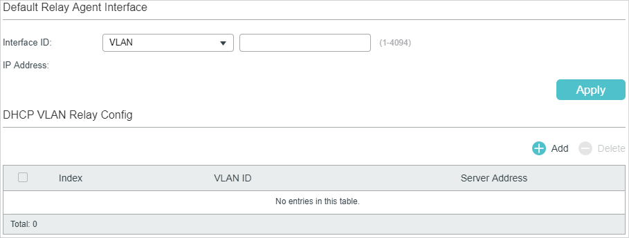
Follow these steps to specify DHCP Server for the specific VLAN:
1)In the Default Relay Agent Interface section, specify a Layer 3 interface as the default relay agent interface. Then click Apply.
|
Interface ID |
Specify the type and ID of the interface that needs to be configured as the default relay agent interface. You can configure any existing layer 3 interface as the default relay agent interface. The DHCP server will assign IP addresses in the same subnet with this relay agent interface to the clients who use this relay agent interface to apply for IP addresses. |
|
IP Address |
Displays the IP address of this interface. |
|
|
Note: If the VLAN the clients belong to already has an IP address, the switch will use the client’s own VLAN interface as the relay agent interface. The manually specified default relay agent will not take effect. A routed port or port channel interface is not associated with a particular VLAN. DHCP VLAN relay will not work on routed ports or port channel interfaces. |
2)In the DHCP VLAN Relay Config section, click to load the configuration page.
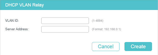
Specify the VLAN the clients belongs to and the server address. Click Create.
|
VLAN ID |
Specify the VLAN, in which the clients can get IP addresses from the DHCP server. |
|
Server Address |
Enter the IP address of the DHCP server. |
3.2.1Enabling DHCP Relay
Follow these steps to enable DHCP Relay and configure the corresponding parameters:
|
Step 1 |
configure Enter global configuration mode. |
|
Step 2 |
service dhcp relay Enable DHCP Relay. |
|
Step 3 |
ip dhcp relay hops hops Specify the maximum hops (DHCP Relay agent) that the DHCP packets can be relayed. If a packet’s hop count is more than the value you set here, the packet will be dropped. hops: Specify the maximum hops for DHCP packets. The valid value ranges from the 1 to 16, and the default value is 4. |
|
Step 4 |
ip dhcp relay time time Specify the DHCP relay time threshold. DHCP relay time is the time elapsed since client began address acquisition or renewal process. When the elapsed time of the DHCP packet is greater than the value set here, the DHCP packet will be dropped by the switch. time: Specify the DHCP relay time threshold. The valid value ranges from 1 to 65535. The default value is 0, which means the switch will not examine this field of the DHCP packets. |
|
Step 5 |
show ip dhcp relay Verify the configuration of DHCP Relay. |
|
Step 6 |
end Return to Privileged EXEC Mode. |
|
Step 7 |
copy running-config startup-config Save the settings in the configuration file. |
The following example shows how to enable DHCP Relay, configure the relay hops as 5 and configure the relay time as 10 seconds :
Switch#configure
Switch(config)#service dhcp relay
Switch(config)#show ip dhcp relay
Switch(config)#ip dhcp relay hops 5
Switch(config)#ip dhcp relay time 10
DHCP relay state: enabled
DHCP relay hops: 5
DHCP relay Time Threshold: 10 seconds
...
Switch(config)#end
Switch#copy running-config startup-config
3.2.2(Optional) Configuring Option 82
Follow these steps to configure Option 82:
|
Step 1 |
configure Enter global configuration mode. |
|
Step 2 |
interface { fastEthernet port | range fastEthernet port-list | gigabitEthernet port | range gigabitEthernet port-list | ten-gigabitEthernet port | range ten-gigabitEthernet port-list } Enter interface configuration mode. |
|
Step 3 |
ip dhcp relay information option Enable the Option 82 feature on the port. |
|
Step 4 |
ip dhcp relay information strategy { keep | replace | drop } Specify the operation for the Option 82 field of the DHCP request packets from the Host. The following options are provided: keep: Indicates keeping the Option 82 field of the packets. replace: Indicates replacing the Option 82 field of the packets with one defined by switch. By default, the Circuit ID is defined to be the VLAN and the number of the port which receives the DHCP Request packets. The Remote ID is defined to be the MAC address of the DHCP Snooping device which receives the DHCP Request packets. drop: Indicates discarding the packets that include the Option 82 field. |
|
Step 5 |
ip dhcp relay information format { normal | private } Specify the format of option 82 sub-option value field. normal: Indicates that the format of sub-option value field is TLV (type-length-value). private: Indicates that the format of sub-option value field is the value you configure for the related sub-option. |
|
Step 6 |
ip dhcp relay information circuit-id string Configure the circuit ID. The circuit ID configurations of the switch and the DHCP server should be compatible with each other. string: Enter the circuit ID, which contains up to 64 characters. |
|
Step 7 |
ip dhcp relay information remote-id string Configure the remote ID. The remote ID configurations of the switch and the DHCP server should be compatible with each other. string: Enter the remote ID, which contains up to 64 characters. |
|
Step 8 |
show ip dhcp relay information interface { fastEthernet port | gigabitEthernet port | ten-gigabitEthernet port | port-channel port-channel-id } Verify the Option 82 configuration of the port. |
|
Step 9 |
end Return to Privileged EXEC Mode. |
|
Step 10 |
copy running-config startup-config Save the settings in the configuration file. |
The following example shows how to enable Option 82 on port 1/0/7 and configure the strategy as replace, the format as normal, the circuit-id as VLAN20 and the remote-id as Host1:
Switch#configure
Switch(config)#interface gigabitEthernet 1/0/7
Switch(config-if)#ip dhcp relay information option
Switch(config-if)#ip dhcp relay information strategy replace
Switch(config-if)#ip dhcp relay information format normal
Switch(config-if)#ip dhcp relay information circut-id VLAN20
Switch(config-if)#ip dhcp relay information remote-id Host1
Switch(config-if)#show ip dhcp relay information interface gigabitEthernet 1/0/7
Interface Option 82 Status Operation Strategy Format Circuit ID Remote ID LAG
--------- ---------------- ------------------ ------- --------- -------- -----
Gi1/0/7 Enable Replace Normal VLAN20 Host1 N/A
Switch(config-if)#end
Switch#copy running-config startup-config
3.2.3Configuring DHCP Interface Relay
You can specify DHCP server for an Layer 3 interface or for a VLAN. The following respectively introduces how to configure DHCP Interface Relay and DHCP VLAN Relay.
Follow these steps to DHCP Interface Relay:
|
Step 1 |
configure Enter global configuration mode. |
|
Step 2 |
Enter Layer 3 interface configuration mode: Enter VLAN interface configuration mode: interface vlan vlan-id vlan-id: Specify an IEEE 802.1Q VLAN ID that already exists, ranging from 1 to 4094. Enter routed port configuration mode: interface { fastEthernet port | gigabitEthernet port | ten-gigabitEthernet port } Enter interface configuration mode. port: Specify the Ethernet port number, for example 1/0/1. no switchport Switch the Layer 2 port into the Layer 3 routed port. Enter port-channel interface configuration mode: interface { port-cahnnel port-channel } Enter interface configuration mode. port-channel: Specify the port channel, the valid value ranges from 1 to 14. no switchport Switch the port channel to a Layer 3 port channel interface. |
|
Step 3 |
ip helper-address ip-addr Specify DHCP server for the Layer 3 interface. ip-addr: Enter the IP address of the DHCP server. |
|
Step 4 |
show ip dhcp relay Verify the configuration of DHCP Relay. |
|
Step 5 |
end Return to Privileged EXEC Mode. |
|
Step 6 |
copy running-config startup-config Save the settings in the configuration file. |
The following example shows how to configure the DHCP server address as 192.168.1.7 on VLAN interface 66:
Switch#configure
Switch(config)#interface vlan 66
Switch(config-if)#ip helper-address 192.168.1.7
Switch(config-if)#show ip dhcp relay
...
DHCP relay helper address is configured on the following interfaces:
Interface Helper address
---------- --------------
VLAN 66 192.168.1.7
Switch(config-if)#end
Switch#copy running-config startup-config
3.2.4Configuring DHCP VLAN Relay
Follow these steps to configure DHCP VLAN Relay:
|
Step 1 |
configure Enter global configuration mode. |
|
Step 2 |
Enter Layer 3 interface configuration mode: Enter VLAN interface configuration mode: interface vlan vlan-id vlan-id: Specify an IEEE 802.1Q VLAN ID that already exists, ranging from 1 to 4094. Enter routed port configuration mode: interface { fastEthernet port | gigabitEthernet port | ten-gigabitEthernet port } Enter interface configuration mode. port: Specify the Ethernet port number, for example 1/0/1. no switchport Switch the Layer 2 port into the Layer 3 routed port. Enter port-channel interface configuration mode: interface { port-cahnnel port-channel } Enter interface configuration mode. port-channel: Specify the port channel, the valid value ranges from 1 to 14. no switchport Switch the port channel to a Layer 3 port channel interface. |
|
Step 3 |
ip dhcp relay default-interface Set the interface as the default relay agent interface. If the VLAN that the clients belong to does not have an IP address, the switch will use the IP address of this interface to fill in the relay agent IP address field of DHCP packets from the DHCP clients. |
|
Step 4 |
exit Return to global configuration mode. |
|
Step 5 |
ip dhcp relay vlan vid helper-address ip-address Specify the VLAN ID and the DHCP server. vid: Enter the ID of the VLAN, in which the hosts can dynamically get the IP addresses from the DHCP server. ip-address: Enter the IP address of the DHCP server. |
|
Step 6 |
show ip dhcp relay Verify the configuration of DHCP Relay. |
|
Step 7 |
end Return to Privileged EXEC Mode. |
|
Step 8 |
copy running-config startup-config Save the settings in the configuration file. |
The following example shows how to set the routed port 1/0/2 as the default relay agent interface and configure the DHCP server address as 192.168.1.8 on VLAN 10:
Switch#configure
Switch(config)#interface gigabitEthernet 1/0/2
Switch(config-if)#no switchport
Switch(config-if)# ip dhcp relay default-interface
Switch(config-if)#exit
Switch(config)#ip dhcp relay vlan 10 helper-address 192.168.1.8
Switch(config)#show ip dhcp relay
...
DHCP VLAN relay helper address is configured on the following vlan:
vlan Helper address
---------- --------------
VLAN 10 192.168.1.8
Switch(config)#end
Switch#copy running-config startup-config
To complete DHCP L2 Relay configuration, follow these steps:
1)Enable DHCP L2 Relay.
2)Configure Option 82 for ports.
4.1.1Enabling DHCP L2 Relay
Choose the menu L3 FEATURES > DHCP Service > DHCP L2 Relay > Global Config to load the following page.
Figure 4-1 Enable DHCP L2 Relay
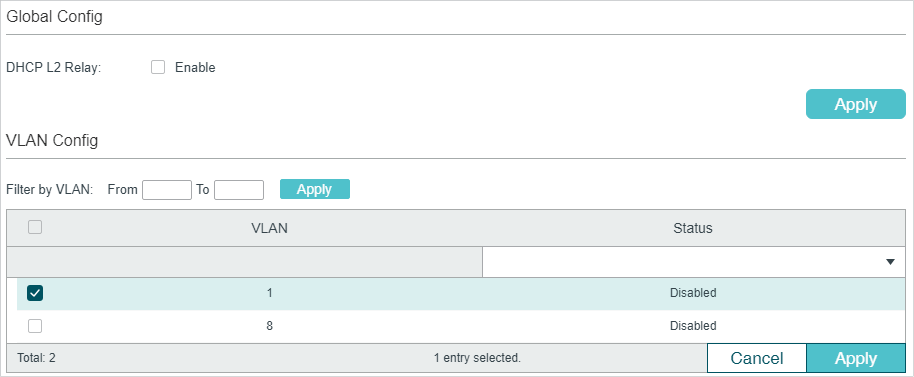
Follow these steps to enable DHCP L2 Relay globally and for the specified VLAN:
1)In the Global Config section, enable DHCP L2 Relay globally. Click Apply.
|
DHCP L2 Relay |
Enable DHCP Relay globally. |
2)In the VLAN Config section, enable DHCP L2 Relay for the specified VLAN. Click Apply.
|
VLAN |
Displays the VLAN ID. |
|
Status |
Enable DHCP L2 Relay for the specified VLAN.. |
4.1.1Configuring Option 82 for Ports
Choose the menu L3 FEATURES > DHCP Service > DHCP L2 Relay > Port Config to load the following page.
Figure 4-1 Configure Option 82 for Ports
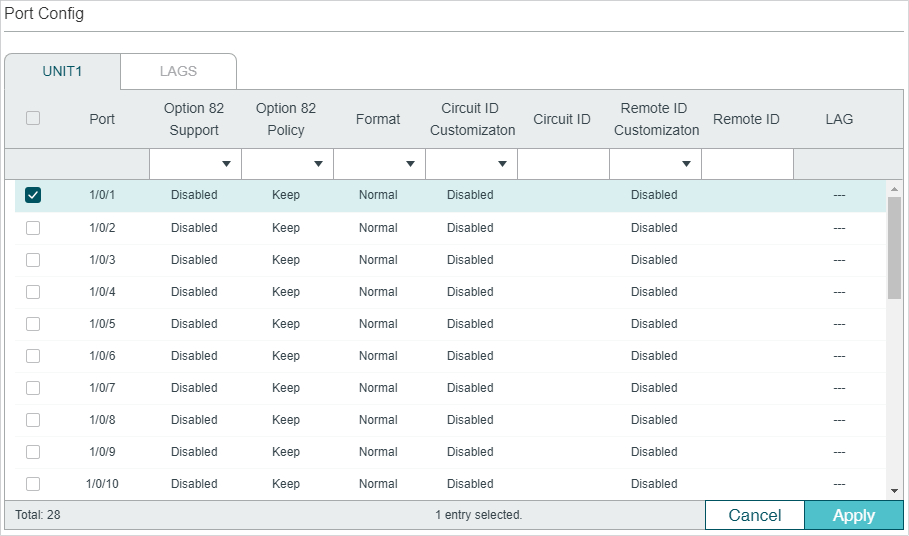
Follow these steps to enable DHCP Relay and configure Option 82:
1)Select one or more ports to configure Option 82.
|
Option 82 Support |
Select whether to enable Option 82 or not. By default, it is disabled. Option 82 is used to record the DHCP client’s location, Ethernet port and the VLAN, etc. If you need to record the accurate location of a client, you can enable Option 82 on the relay device which is closest to the client. |
|
Option 82 Policy |
Select the operation for the Option 82 field of the DHCP request packets. Keep: Indicates keeping the Option 82 field of the packets. Replace: Indicates replacing the Option 82 field of the packets with the switch defined one. By default, the Circuit ID is defined to be the VLAN and the ID of the port which receives the DHCP Request packets. The Remote ID is defined to be the MAC address of the DHCP Relay device which receives the DHCP Request packets. Drop: Indicates discarding the packets that include the Option 82 field. |
|
Format |
Select the format of option 82 sub-option value field. Normal: Indicates that the format of sub-option value field is TLV (type-length-value). Private: Indicates that the format of sub-option value field is just value. |
|
Circuit ID Customization |
Enable or disable Customization of Option 82. If enabled, you need to configure Option 82 information manually; If disabled, the switch will automatically configure the VLAN ID and the ID of the port that receives the DHCP packets as the circuit ID. |
|
Circuit ID |
Enter the customized circuit ID, which contains up to 64 characters. The circuit ID configurations of the switch and the DHCP server should be compatible with each other. |
|
Remote ID Customization |
Enable or disable the switch to define the Option 82 sub-option Remote ID field. If it is enabled, you can manually configure the remote ID; if it is disabled, the switch will automatically configure the switch’s MAC address as the remote ID. |
|
Remote ID |
Enter the customized remote ID, which contains up to 64 characters. The remote ID configurations of the switch and the DHCP server should be compatible with each other. |
2)Click Apply
4.2.1Enabling DHCP L2 Relay
Follow these steps to enable DHCP L2 Relay:
|
Step 1 |
configure Enter global configuration mode. |
|
Step 2 |
ip dhcp l2relay Enable DHCP L2 Relay. |
|
Step 3 |
ip dhcp l2relay vlan valn-list Enable DHCP L2 Relay for specified VLANs. vlan-list: Specify the vlan to be enabled with DHCP L2 relay. |
|
Step 5 |
show ip dhcp l2relay Verify the configuration of DHCP Relay. |
|
Step 6 |
end Return to Privileged EXEC Mode. |
|
Step 7 |
copy running-config startup-config Save the settings in the configuration file. |
The following example shows how to enable DHCP L2 Relay globally and for VLAN 2:
Switch#configure
Switch(config)#ip dhcp l2relay
Switch(config)#ip dhcp l2relay vlan 2
Switch(config)#show ip dhcp l2relay
Global Status: Enable
VLAN ID: 2
Switch(config)#end
Switch#copy running-config startup-config
4.2.2Configuring Option 82 for Ports
Follow these steps to configure Option 82:
|
Step 1 |
configure Enter global configuration mode. |
|
Step 2 |
interface { fastEthernet port | range fastEthernet port-list | gigabitEthernet port | range gigabitEthernet port-list | ten-gigabitEthernet port | range ten-gigabitEthernet port-list } Enter interface configuration mode. |
|
Step 3 |
ip dhcp l2relay information option Enable the Option 82 feature on the port. |
|
Step 4 |
ip dhcp l2relay information strategy { keep | replace | drop } Specify the operation for the Option 82 field of the DHCP request packets from the Host. The following options are provided: keep: Indicates keeping the Option 82 field of the packets. replace: Indicates replacing the Option 82 field of the packets with one defined by switch. By default, the Circuit ID is defined to be the VLAN and the number of the port which receives the DHCP Request packets. The Remote ID is defined to be the MAC address of the DHCP Snooping device which receives the DHCP Request packets. drop: Indicates discarding the packets that include the Option 82 field. |
|
Step 5 |
ip dhcp l2relay information format { normal | private } Specify the format of option 82 sub-option value field. normal: Indicates that the format of sub-option value field is TLV (type-length-value). private: Indicates that the format of sub-option value field is the value you configure for the related sub-option. |
|
Step 6 |
ip dhcp l2relay information circuit-id string Configure the circuit ID. The circuit ID configurations of the switch and the DHCP server should be compatible with each other. string: Enter the circuit ID, which contains up to 64 characters. |
|
Step 7 |
ip dhcp l2relay information remote-id string Configure the remote ID. The remote ID configurations of the switch and the DHCP server should be compatible with each other. string: Enter the remote ID, which contains up to 64 characters. |
|
Step 8 |
show ip dhcp l2relay information interface { fastEthernet port | gigabitEthernet port | port-channel port-channel-id } Verify the Option 82 configuration of the port. |
|
Step 9 |
end Return to Privileged EXEC Mode. |
|
Step 10 |
copy running-config startup-config Save the settings in the configuration file. |
The following example shows how to enable Option 82 on port 1/0/7 and configure the strategy as replace, the format as normal, the circuit-id as VLAN20 and the remote-id as Host1:
Switch#configure
Switch(config)#interface gigabitEthernet 1/0/7
Switch(config-if)#ip dhcp l2relay information option
Switch(config-if)#ip dhcp l2relay information strategy replace
Switch(config-if)#ip dhcp l2relay information format normal
Switch(config-if)#ip dhcp l2relay information circut-id VLAN20
Switch(config-if)#ip dhcp l2relay information remote-id Host1
Switch(config-if)#show ip dhcp l2relay information interface gigabitEthernet 1/0/7
Interface Option 82 Status Operation Strategy Format Circuit ID Remote ID LAG
--------- ---------------- ------------------ ------- --------- -------- -----
Gi1/0/7 Enable Replace Normal VLAN20 Host1 N/A
Switch(config-if)#end
Switch#copy running-config startup-config
5.1Example for DHCP Server
5.1.1Network Requirements
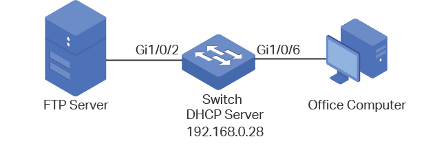
As the network topology shows, the administrator uses the switch as the DHCP server to assign IP addresses to all the connected devices. The office computers need to obtain IP addresses dynamically, while the FTP server need to be assigned a fixed IP address.
Figure 5-1 Network Topology for DHCP Server
5.1.2Configuration Scheme
You can enable the DHCP Server service on the switch and create a DHCP IP pool for all the connected devices. Then manually bind the MAC address of the FTP server to an IP address specified for the FTP server.
Demonstrated with T2600G-52TS, this chapter provides configuration procedures in two ways: using the GUI and using the CLI.
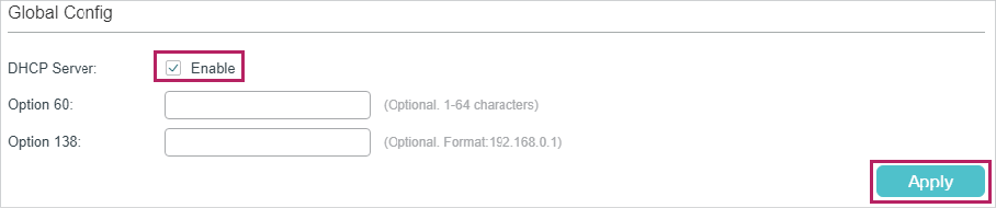
5.1.3Using the GUI
1)Choose the menu L3 FEATURES > DHCP Service > DHCP Server > DHCP Server to load the following page. In the Global Config section, enable DHCP Server.
Figure 5-2 Configuring DHCP Server
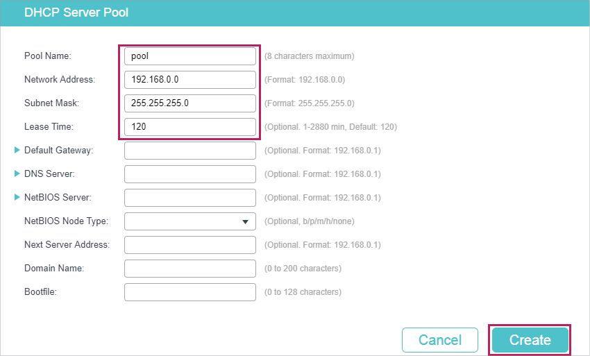
2)Choose the menu L3 FEATURES > DHCP Service > DHCP Server > Pool Setting and click to load the following page. Specify the Pool Name, Network Address, Subnet Mask, Lease Time, Default Gateway and DNS Server as shown below. Click Create.
Figure 5-3 Configuring DHCP Server Pool
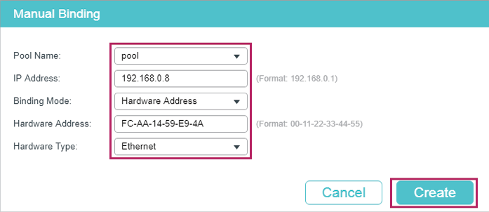
3)Choose the menu L3 FEATURES > DHCP Service > DHCP Server > Manual Binding and click to load the following page. Select the DHCP server pool you just created, and enter the IP address of the FTP server in the IP Address field. Select Hardware Address as the binding mode, and enter the MAC address of the FTP server in the Hardware Address field. Select Ethernet as the Hardware Type. Click Create.
Figure 5-4 Configuring Manual Binding
4) Click  to save the settings.
5.1.4Using the CLI
1)Enable DHCP Server.
Switch#configure
Switch(config)#service dhcp server
2)Specify the Pool Name, Network Address, Subnet Mask and Lease Time.
Switch(config)#ip dhcp server pool pool
Switch(dhcp-config)#network 192.168.0.0 255.255.255.0
Switch(dhcp-config)#lease 120
Switch(dhcp-config)#exit
3)Bind the specified IP address to the MAC address of the FTP server.
Switch(config)# ip dhcp server pool pool
Switch(dhcp-config)# address 192.168.0.8 hardware-address FC-AA-14-59-E9-4A hardware-type ethernet
Switch(dhcp-config)#end
Switch#copy running-config startup-config
Verify the Configuration
Switch#show ip dhcp server binding
IP Address Client id/Hardware Address Type Lease Time Left
---------- -------------------------- --------- ---------------
192.168.0.2 01-d43d-7ebf-615f Automatic 01:57:27
192.168.0.8 01-fcaa-1459-e94a Manual Infinite
5.2Example for DHCP Interface Relay
5.2.1Network Requirements
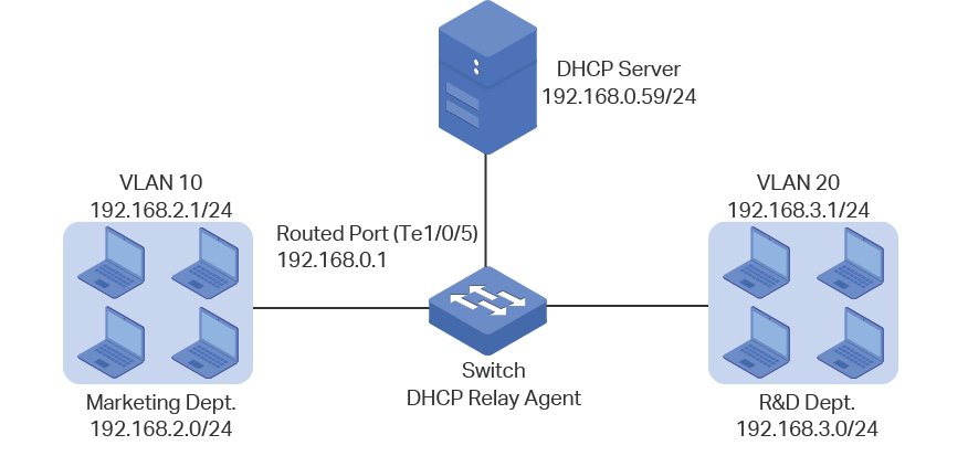
The administrator deploys one DHCP server on the network, and want the server to assign IP addresses to the computers in the Marketing department and the R&D department . It is required that computers in the same department should be on the same subnet, while computers in different departments should be on different subnets.
As the network topology shows, the Marketing department and the R&D department respectively belong to VLAN 10 and VLAN 20. The IP address of VLAN interface 10 is 192.168.2.1 and the IP address of VLAN interface 20 is 192.168.3.1. The DHCP server is connected to the routed port of the switch. The Marketing department is connected to port 1/0/1 of the relay agent and the R&D department is connected to port 1/0/2 of the relay agent.
Figure 5-5 Network Topology for DHCP Interface Relay
5.2.2Configuration Scheme
In the given situation, the DHCP server and the computers are isolated in different network segments, so the DHCP request from the clients cannot be directly forwarded to the DHCP server. To satisfy the requirement that the two departments are assigned IP addresses in different subnet, we recommend you to configure DHCP Interface Relay to satisfy the requirement.
The overview of the configurations are as follows:
1)Before configuring DHCP Interface Relay, create two DHCP IP pools on the DHCP server, one is on 192.168.2.0/24 network segment and the other is on 192.168.3.0/24 network segment. Then create static routes or enable dynamic routing protocol like RIP on the DHCP server to make sure the DHCP server can reach the clients in the two VLANs.
2)Configure 802.1Q VLAN on the DHCP relay agent. Add all computers in the marketing department to VLAN 10, and add all computers in the R&D department to VLAN 20.
3)Create VLAN interfaces for VLAN 10 and VLAN 20 on the DHCP relay agent.
4)Configure DHCP Interface Relay on the DHCP relay agent. Enable DHCP Relay globally, and specify the DHCP server address for each VLAN.
In this example, the DHCP server is demonstrated with T2600G-52TS and the DHCP relay agent is demonstrated with T1700X-16TS. This chapter provides configuration procedures in two ways: using the GUI and using the CLI.
5.2.3Using the GUI
Configuring the DHCP Server
1)Choose the menu L3 FEATURES > DHCP Service > DHCP Server > DHCP Server to load the following page. In the Global Config section, enable DHCP Server globally.
Figure 5-6 Configuring DHCP Server
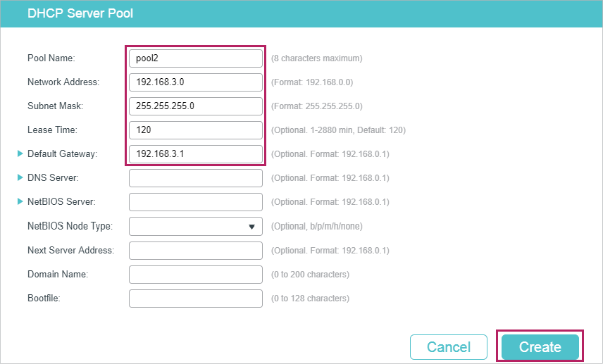
2)Choose the menu L3 FEATURES > DHCP Service > DHCP Server > Pool Setting and click to load the following page. Create pool 1 for VLAN 10 and pool 2 for VLAN 20. Configure the corresponding parameters as the following pictures show.
Figure 5-7 Configuring DHCP Pool 1 for VLAN 10
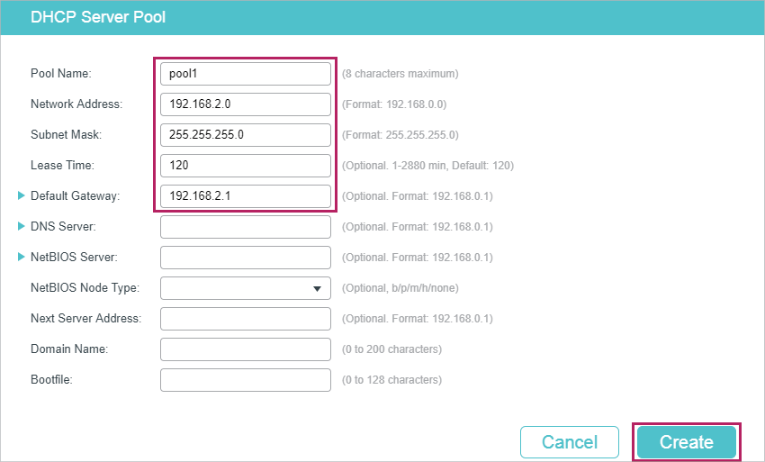
Figure 5-8 Configuring DHCP Pool 2 for VLAN 20
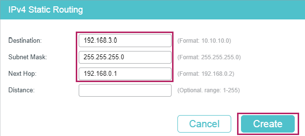
1)Choose the menu L3 FEATURES > Static Routing > IPv4 Static Routing and click to load the following page. Create two static routing entries for the DHCP server to make sure that the DHCP server can reach the clients in the two VLANs.
Figure 5-9 Creating the Static Routing Entry for VLAN 10
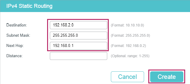
Figure 5-10 Creating the Static Routing Entry for VLAN 20
Configuring the VLANs on the Relay Agent
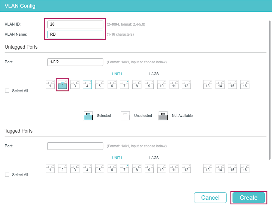
2)Choose the menu L2 FEATURES > VLAN > 802.1Q VLAN > VLAN Config and click to load the following page. Create VLAN 10 and VLAN 20 for the Marketing department and R&D department respectively. Add port 1/0/1 to VLAN 10 and port 1/0/2 to VLAN 20.
Figure 5-11 Creating VLAN 10
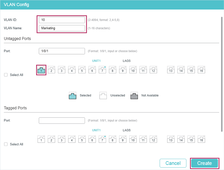
Figure 5-12 Creating VLAN 20
Configuring the VLAN Interface and Routed Port on the Relay Agent
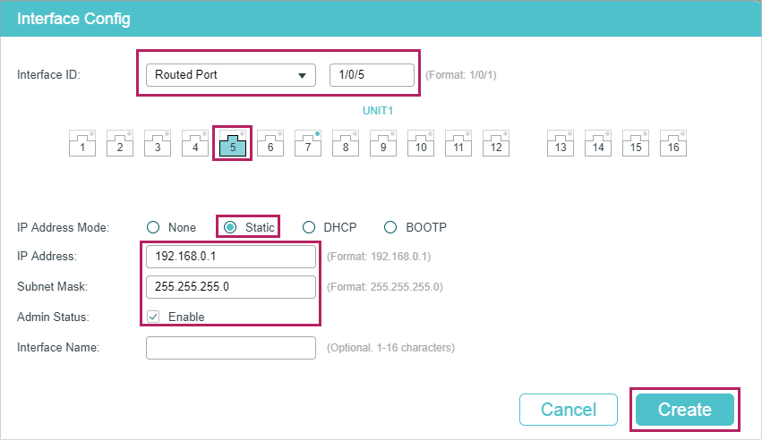
1)Choose the menu L3 FEATURES > Interface and click to load the following page. Create VLAN interface 10 and VLAN interface 20. Configure port 1/0/5 as the routed port.
Figure 5-13 Creating VLAN Interface 10
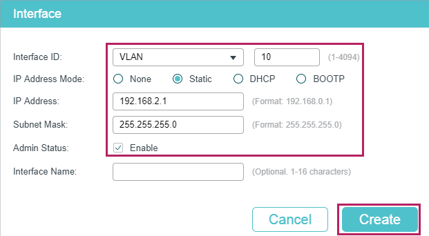
Figure 5-14 Creating VLAN Interface 20
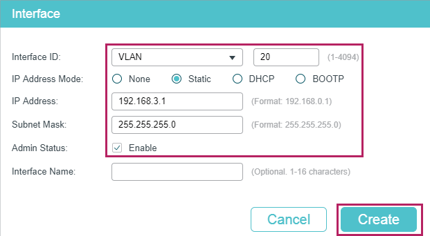
Figure 5-15 Configuring the Routed Port
Configuring DHCP Interface Relay on the Relay Agent
1)Choose the menu L3 FEATURES > DHCP Service > DHCP Relay > DHCP Relay Config to load the following page. In the Global Config section, enable DHCP Relay, and click Apply.
Figure 5-16 Enable DHCP Relay
2)Choose the menu L3 FEATURES > DHCP Service > DHCP Relay > DHCP Interface Relay and click to load the following page. Specify the DHCP server for the clients in VLAN 10 and VLAN 20.
Figure 5-17 Specify DHCP Server for Interface VLAN 10
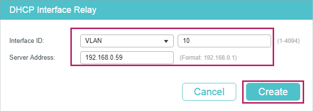
Figure 5-18 Specify DHCP Server for Interface VLAN 20
3)Click  to save the settings.
5.2.4Using the CLI
Configurting the DHCP Server
1)Enable DHCP service globally.
Switch#configure
Switch(config)#service dhcp server
2)Create DHCP pool 1 and configure its network address as 192.168.2.0, subnet mask as 255.255.255.0, lease time as 120 minute, default gateway as 192.168.2.1; Create DHCP pool 2 and configure its network address as 192.168.3.0, subnet mask as 255.255.255.0, lease time as 120 minute, default gateway as 192.168.3.1.
Switch(config)#ip dhcp server pool pool1
Switch(dhcp-config)#network 192.168.2.0 255.255.255.0
Switch(dhcp-config)#lease 120
Switch(dhcp-config)#default-gateway 192.168.2.1
Switch(dhcp-config)#exit
Switch(config)#ip dhcp server pool pool1
Switch(dhcp-config)#network 192.168.2.0 255.255.255.0
Switch(dhcp-config)#lease 120
Switch(dhcp-config)#default-gateway 192.168.2.1
Switch(dhcp-config)#exit
3)Create two static routing entries to make sure that the DHCP server can reach the clients in the two VLANs.
Switch(config)# ip route 192.168.2.0 255.255.255.0 192.168.0.1
Switch(config)# ip route 192.168.3.0 255.255.255.0 192.168.0.1
Switch(config)#end
Switch#copy running-config startup-config
Configuring the VLAN on the Relay Agent
Switch(config)# vlan 10
Switch(config-vlan)#name Marketing
Switch(config-vlan)#exit
Switch(config)#interface ten-gigabitEthernet 1/0/1
Switch(config-if)#switchport general allowed vlan 10 untagged
Switch(config-if)#exit
Switch(config)# vlan 20
Switch(config-vlan)#name RD
Switch(config-vlan)#exit
Switch(config)#interface ten-gigabitEthernet 1/0/2
Switch(config-if)#switchport general allowed vlan 20 untagged
Switch(config-if)#exit
Configuring the VLAN Interfaces Routed Port on the Relay Agent
Switch(config)#interface vlan 10
Switch(config-if)#ip address 192.168.2.1 255.255.255.0
Switch(config-if)#exit
Switch(config)#interface vlan 20
Switch(config-if)#ip address 192.168.3.1 255.255.255.0
Switch(config-if)#exit
Switch(config)#interface ten-gigabitEthernet 1/0/5
Switch(config-if)#ip address 192.168.0.1 255.255.255.0
Switch(config-if)#exit
Configuring DHCP Interface Relay on the Relay Agent
1)Enable DHCP Relay.
Switch#configure
Switch(config)#service dhcp relay
2)Specify the DHCP server for the interface VLAN 10.
Switch(config)#interface vlan 10
Switch(config-if)#ip helper-address 192.168.0.59
Switch(config-if)#exit
3)Specify the DHCP server for interface VLAN 20
Switch(config)#interface vlan 20
Switch(config-if)#ip helper-address 192.168.0.59
Switch(config-if)#end
Switch#copy running-config startup-config
Verify the Configurations of the DHCP Relay Agent
Switch#show ip dhcp relay
DHCP relay is enabled
...
DHCP relay helper address is configured on the following interfaces:
Interface Helper address
--------------------- -------------------------
VLAN10 192.168.0.59
VLAN20 192.168.0.59
...
5.3Example for DHCP VLAN Relay
5.3.1Network Requirements
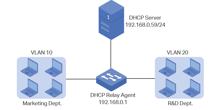
The Marketing department and the R&D department respectively belong to two VLANs. Both of the VLANs have no Layer 3 gateways. The administrator deploys one DHCP server on the network, and wants the server to assign IP addresses to the two departments.
As the network topology shows, the Marketing department and the R&D department respectively belong to VLAN 10 and VLAN 20. The Marketing department is connected to port 1/0/1 of the relay agent and the R&D department is connected to port 1/0/2 of the relay agent.
Figure 5-19 Network Topology for DHCP VLAN Relay
5.3.2Configuration Scheme
In the given situation, the DHCP server and the computers are isolated by VLANs, so the DHCP request from the clients cannot be directly forwarded to the DHCP server. Considering that the two VLANs have no Layer 3 gateways, we recommend you to configure DHCP VLAN Relay to satisfy the requirement.
The overview of the configurations are as follows:
1)Create one DHCP IP pool on the DHCP server, which is on 192.168.0.0/24 network segment.
2)Configure 802.1Q VLAN on the DHCP relay agent. Add all computers in the marketing department to VLAN 10, and add all computers in the R&D department to VLAN 20.
3)Configure DHCP VLAN Relay on the DHCP relay agent. Enable DHCP Relay globally, choose the VLAN interface 1 (the default management VLAN interface) as the default relay agent interface, and specify the DHCP server address for VLAN 10 and VLAN 20.
In this example, the DHCP server is demonstrated with T2600G-28TS and the DHCP relay agent is demonstrated with T1500-28PCT. This chapter provides configuration procedures in two ways: using the GUI and using the CLI.
5.3.3Using the GUI
Configuring the DHCP Server
1)Choose the menu L3 FEATURES > DHCP Service > DHCP Server > DHCP Server to load the following page. In the Global Config section, enable DHCP Server globally.
Figure 5-20 Configuring DHCP Server
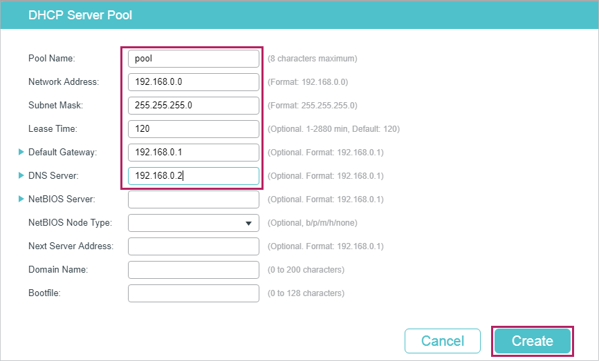
2)Choose the menu L3 FEATURES > DHCP Service > DHCP Server > Pool Setting and click to load the following page. Create a DHCP pool for the clients. Configure the corresponding parameters as the following picture shows.
Figure 5-21 Configuring DHCP Pool 1 for VLAN 10
Configuring the VLANs on the Relay Agent
3)Choose the menu L2 FEATURES > VLAN > 802.1Q VLAN > VLAN Config and click to load the following page. Create VLAN 10 and VLAN 20 for the Marketing department and R&D department respectively. Add port 1/0/1 to VLAN 10 and port 1/0/2 to VLAN 20.
Figure 5-22 Creating VLAN 10

Figure 5-23 Creating VLAN 20
Configuring DHCP VLAN Relay on the Relay Agent
1)Choose the menu L3 FEATURES > DHCP Service > DHCP Relay > DHCP Relay Config to load the following page. In the Global Config section, enable DHCP Relay, and click Apply.
Figure 5-24 Enable DHCP Relay

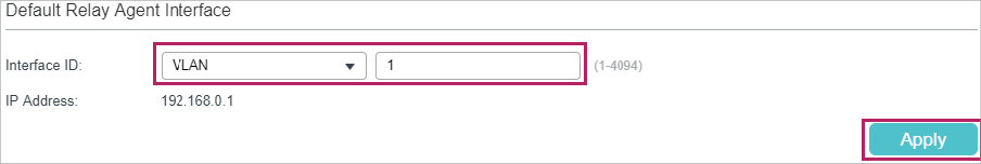
2)Choose the menu L3 FEATURES > DHCP Service > DHCP Relay > DHCP VLAN Relay to load the following page. In the Default Relay Agent Interface section, specify VLAN interface 1 (the default management VLAN interface ) as the default relay agent interface.
Figure 5-25 Specify the Default Relay Agent Interface
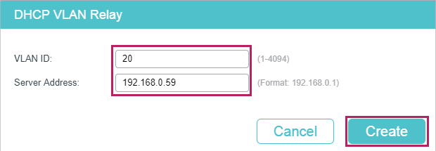
3)Choose the menu L3 FEATURES > DHCP Service > DHCP Relay > DHCP VLAN Relay and click to load the following page. Specify the DHCP server address for the clients in VLAN 10 and VLAN 20.
Figure 5-26 Specify DHCP Server for Interface VLAN 10
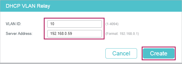
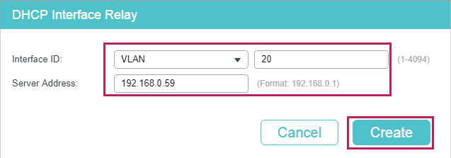
Figure 5-27 Specify DHCP Server for Interface VLAN 20
4)Click to save the settings.
5.3.4Using the CLI
Configurting the DHCP Server
1)Enable DHCP service globally.
Switch#configure
Switch(config)#service dhcp server
2)Create a DHCP pool and name it as “pool” and configure its network address as 192.168.0.0, subnet mask as 255.255.255.0, lease time as 120 minute, default gateway as 192.168.0.1.
Switch(config)#ip dhcp server pool pool
Switch(dhcp-config)#network 192.168.0.0 255.255.255.0
Switch(dhcp-config)#lease 120
Switch(dhcp-config)#default-gateway 192.168.0.1
Switch(dhcp-config)#dns-server 192.168.0.2
Switch(dhcp-config)#end
Switch#copy running-config startup-config
Configuring the VLAN on the Relay Agent
Switch#configure
Switch(config)# vlan 10
Switch(config-vlan)#name Marketing
Switch(config-vlan)#exit
Switch(config)#interface fastEthernet 1/0/1
Switch(config-if)#switchport general allowed vlan 10 untagged
Switch(config-if)#exit
Switch(config)# vlan 20
Switch(config-vlan)#name RD
Switch(config-vlan)#exit
Switch(config)#interface fastEthernet 1/0/2
Switch(config-if)#switchport general allowed vlan 20 untagged
Switch(config-if)#exit
Configuring DHCP VLAN Relay on the Relay Agent
1)Enable DHCP Relay.
Switch(config)#service dhcp relay
2)Specify the routed port 1/0/5 as the default relay agent interface.
Switch(config)#interface vlan 1
Switch(config-if)#ip dhcp relay default-interface
Switch(config-if)#exit
3)Specify the DHCP server for VLAN 10 and VLAN 20
Switch(config)#ip dhcp relay vlan 10 helper-address 192.168.0.59
Switch(config)#ip dhcp relay vlan 20 helper-address 192.168.0.59
Switch(config)#exit
Verify the Configurations of the DHCP Relay Agent
Switch#show ip dhcp relay
Switch#show ip dhcp relay
DHCP relay state: enabled
...
DHCP relay default relay agent interface:
Interface: VLAN 1
IP address: 192.168.0.1
DHCP vlan relay helper address is configured on the following vlan:
vlan Helper address
--------------------- -------------------------
VLAN 10 192.168.0.59
VLAN 20 192.168.0.59
5.4Example for DHCP L2 Relay
5.4.1Network Requirements
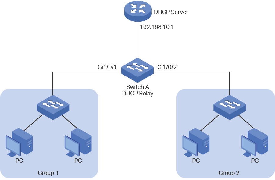
As the following figure shows, two groups are connected to Switch A, and Switch A is connected to the DHCP server. All devices on the network are in the default VLAN1. For management convenience, there are the network requirements:
All PCs on the network get dynamic IP addresses from the DHCP server.
For Group1, the DHCP server assigns the IP addresses from 192.168.10.100 to 192.168.10.150.
For Group2, the DHCP server assigns IP addresses from 192.168.10.151 to 192.168.10.200.
Switch A acts as the DHCP Relay to inform the DHCP server of the group information.
Figure 5-1 Network Topology for DHCP L2 Relay
5.4.2Configuration Scheme
First, make sure that the DHCP server supports Option 82. Then you can configure DHCP L2 Relay on Switch A to inform the DHCP server of the group information of each PC, so that the DHCP server can assign different IP address to the PCs in different groups.
The detailed configurations on the DHCP server may be different among different devices. The general configuration is to create two IP address pools for the two groups and configure the server to identify the DHCP packets from different groups through the option 82. You can refer to the related document that is for the DHCP server.
This chapter introduces the configurations on Switch A, which acts as the DHCP Relay. The configuration overview is as follows:
1)Enable DHCP L2 Relay globally and on VLAN1.
2)Configure Option 82 on ports 1/0/1 and 1/0/2.
Demonstrated with T1500-28PCT, this chapter provides configuration procedures in two ways: using the GUI and using the CLI.
5.4.3Using the GUI
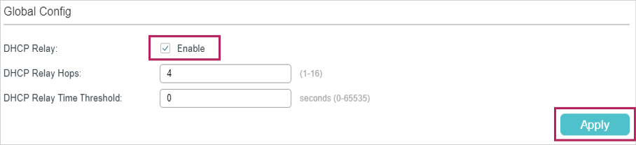
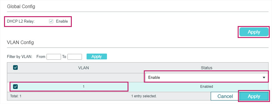
1)Choose the menu L3 FEATURES > DHCP Service > DHCP L2 Relay > Global Config to load the following page. In the Global Config section, enable DHCP L2 Relay globally and click Apply. Enable DHCP L2 Relay on VLAN 1 and click Apply.
Figure 5-2 Enabling DHCP L2 Relay
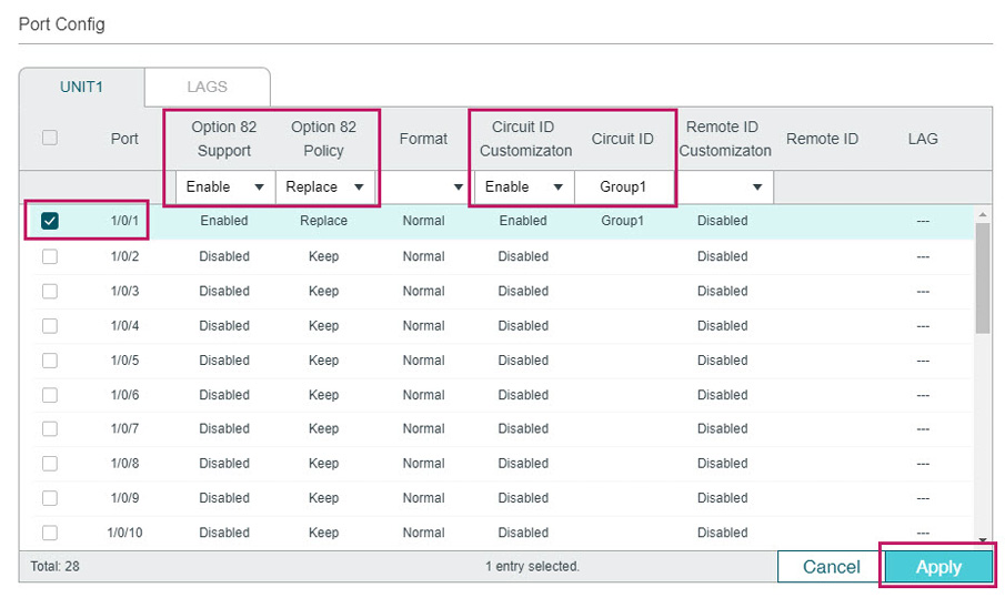
2)Choose the menu L3 FEATURES > DHCP Service > DHCP L2 Relay > Port Config to load the following page. Select port 1/0/1, enable Option 82, select Option 82 Policy as Replace, enable Circuit ID Customization and specify the Circuit ID as Group1. Click Apply.
Figure 5-3 Configuring Port 1/0/1
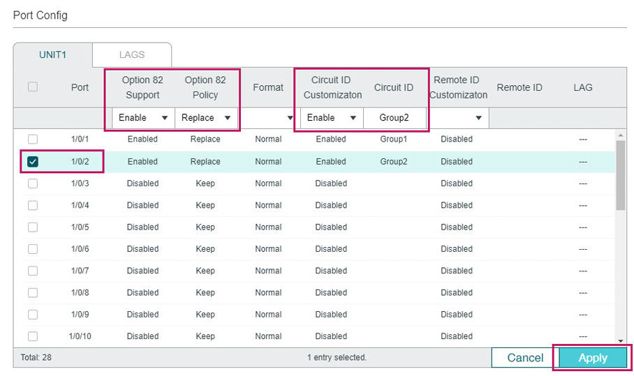
3)On the same page, select port 1/0/2, enable Option 82, select Option 82 Policy as Replace, enable Circuit ID Customization and specify the Circuit ID as Group2. Click Apply.
Figure 5-4 Configuring Port 1/0/2
4)Click  to save the settings.
5.4.4Using CLI
1)Enable DHCP L2 Relay globally and on VLAN1.
Switch#configure
Switch(config)#ip dhcp l2relay
Switch(config)#iip dhcp l2relay vlan 1
2)On port 1/0/1, enable Option 82, set Option 82 Policy to Replace, enable Circuit ID Customization and specify the Circuit ID as Group1.
Switch(config)#interface gigabitEthernet 1/0/1
Switch(config-if)#ip dhcp l2relay information
Switch(config-if)#ip dhcp l2relay information strategy replace
Switch(config-if)#ip dhcp l2relay information circuit-id Group1
Switch(config-if)#exit
3)On port 1/0/2, enable Option 82, set Option 82 Policy to Replace, and specify the Circuit ID as Group2.
Switch(config)#interface gigabitEthernet 1/0/2
Switch(config-if)#ip dhcp l2relay information
Switch(config-if)#ip dhcp l2relay information strategy replace
Switch(config-if)#ip dhcp l2relay information circuit-id Group2
Switch(config-if)#end
Switch#copy running-config startup-config
Verify the Configurations
View global settings:
Switch#show ip dhcp l2relay
Global Status: Enable
VLAN ID: 1
View port settings:
Switch#show ip dhcp l2relay information interface gigabitEthernet 1/0/1
Interface Option 82 Status Operation Strategy Format Circuit ID ...
--------- ---------------- ------------------ ------- --------- ...
Gi1/0/1 Enable Replace Normal Group1 ...
Switch#show ip dhcp l2relay information interface gigabitEthernet 1/0/1
Interface Option 82 Status Operation Strategy Format Circuit ID ...
--------- ---------------- ------------------ ------- --------- ...
Gi1/0/2 Enable Replace Normal Group2 ...
Default settings of DHCP Relay are listed in the following table.
Table 6-1Default Settings of DHCP Relay
|
Parameter |
Default Setting |
|
DHCP Relay |
|
|
DHCP Relay |
Disable |
|
DHCP Relay Hops |
4 |
|
DHCP Relay Time Threshold |
0 |
|
Option 82 Configuration |
|
|
Option 82 Support |
Disabled |
|
Option 82 Policy |
Keep |
|
Format |
Normal |
|
Circuit ID Customization |
Disable |
|
Circuit ID |
None |
|
Remote ID Customization |
Disabled |
|
Remote ID |
None |
Default settings of DHCP L2 Relay are listed in the following table.
Table 6-2Default Settings of DHCP L2 Relay
|
Parameter |
Default Setting |
|
Global Config |
|
|
DHCP Relay |
Disabled |
|
VLAN Status |
Disabled |
|
Port Config |
|
|
Option 82 Support |
Disabled |
|
Option 82 Policy |
Keep |
|
Format |
Normal |
|
Circuit ID Customization |
Disable |
|
Circuit ID |
None |
|
Remote ID Customization |
Disabled |
|
Remote ID |
None |